Although I had completed a project using a servo motor with the Sparkfun ThingPlus ESP32-S2 Wroom here:
New IoT device with a servo motor
turns out that to drive any motor more serious you’ll need a dedicated motor driver board and a separate power supply just for the motors. Luckily Adafruit has just such a board available:
https://core-electronics.com.au/dc-motor-stepper-featherwing-add-on-for-all-feather-boards.html
with the details here:
https://learn.adafruit.com/adafruit-stepper-dc-motor-featherwing
This board will allow you to drive up to 4 independent motors.

which you connect to M1, M2, M3 or M4 shown above.

Flipping the board over, you’ll also find the connection for the external power (5-12V DC) required to actually drive the motors. I decided to use 4 x AA batteries in a separate holder with an on/off switch:
https://core-electronics.com.au/4-x-aa-battery-holder-with-on-off-switch.html

I also got a Mini Robot Rover chassis kit:
https://littlebirdelectronics.com.au/products/mini-robot-rover-chassis-kit-2wd-with-dc-motors

that, as you can from the above, includes 2 x DC motors.
I connected these to M1 and M2 on the motor driver board, as well as also connecting up the external power for the motors.

I then needed to connect 3.3V and GND to the motor driver board which are shown above and in more detail here:
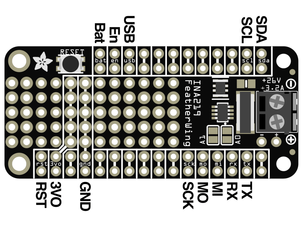
The final piece of the puzzle is to connect the SDA and SCL pins from the Sparkfun ThingPlus ESP32-S2 Wroom to the SDA and SCL pins on the motor driver so they can communicate.
To talk to the motor driver board you’ll need to use the Adafruit motor shield v2 library. I’ll cover off some of the code I’ve created in an upcoming post.
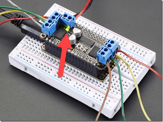
When you apply the power supply for the motors to this board a green LED is lit just under the power connector as shown above. I wasted a few hours with this until I discovered a fault solder joint that was the cause of my issues.
So my wiring looks like:

with the two motors for the drive wheels connected to M1 and M2 as mentioned above and whole thing sitting on the mini robot rover chasis.
I now have a mobile device I can command to move about the room. Next step is actually writing the code to make it work, which I’ll cover off in an upcoming post, so stay tuned. However, here’s a sneak peak of what I managed to do:

One thought on “IoT motor connectivity”